Appendix
Expansion Boards for micro:bit
แผงวงจรขยายความสามารถของ micro:bit
- The micro:bit is capable on its own, but its edge connector is hard to wire and its power is small.
- An expansion board (แผงวงจรขยายความสามารถ) fixes that: the micro:bit plugs into it and gets power, easy pins and motor drivers.
- This appendix covers three popular INEX boards: one for prototyping, one for learning and one for robots.
Why Use Expansion Boards? ทำไมต้องใช้แผงวงจรขยายความสามารถ
Problem 1: the pins are hard to use
- The edge connector has 5 big 4 mm rings: 0, 1, 2, 3V and GND.
- All the other pins are very small gold pads. Ordinary wires do not grip them.
- A board brings every pin out to a plug or socket you can wire easily.
Problem 2: the power is too small
- The micro:bit's own 3.3 V supply gives up to about 300 mA. That is too little for strong loads.
- DC motors and servo motors need 5 V to 6 V and often several hundred mA.
- So a board brings its own power circuits and motor drivers.
The 3 INEX expansion boards at a glance
| Feature | PROJECT:BIT | AX-microBIT+ | iBIT+ |
|---|---|---|---|
| Part number | #7200665 | #830032 | #8000480 |
| micro:bit mount | Socket | 80-pin, upright or flat | 80-pin |
| Power in | +5 V and +3 V circuits | DC jack +5 to +16 V | Jack or screw terminal, +4.8 to +16 V |
| Servo ports | 4 (P8, P12, P13, P14) | None listed | 2 (P8, P12), +6 V |
| DC motor drivers | None | None | 2 × 1 A H-bridge |
| Analog extras | None | Knob on P2 | ADS7828, 8 channels, 12-bit |
| I2C port | 4-pin IDC | None listed | SDA and SCL |
| Clip rings (4 mm) | None | 5: P0, P1, P2, +3V, GND | 5: P0, P1, P2, +3V, GND |
Which board for which project?
PROJECT:BIT (#7200665) บอร์ดอินพุตเอาต์พุตขนาดเล็กสำหรับ micro:bit
- A small input/output board with IDC connectors.
- Good for building many kinds of projects and inventions.
- Only 67 × 50 mm.
Block diagram
Technical features
- A socket that holds the micro:bit.
- Push buttons wired to micro:bit buttons A and B, for easy use.
- 9 three-pin male IDC connectors: P0, P1, P2, P8, P12, P13, P14, P15 and P16, for sensors and outside devices.
- I2C bus connector: 4-pin male-female IDC, for an OLED screen or a digital I2C sensor.
- 4 servo motor connectors: on P8, P12, P13 and P14.
- Dual power circuits: +5 V for servos, and a steady +3 V for the whole board including the micro:bit.
- Metal standoffs with M3 threads, so the board mounts easily on a frame or base plate.
AX-microBIT+ (#830032) บอร์ดอินพุตเอาต์พุตสำหรับการเรียนรู้
- A learning board with a flat connector, so the micro:bit can be mounted upright or flat.
Block diagram
Technical features
- 80-pin connectors, upright and flat, for the micro:bit.
- An on/off switch for the board.
- A DC jack for +5 V power, a steady +3.3 V circuit and reverse-polarity protection.
- JST connectors for the important ports, to join INEX input/output devices.
- Every micro:bit port as male and female IDC, so wiring to a breadboard is easy.
- Five 4 mm gold-plated rings for crocodile clips, wired to P0, P1, P2, +3V and GND.
- Two push buttons wired to micro:bit buttons A and B.
- Potentiometer on the board: read analog input on P2 straight away.
- Two-layer PTH circuit board, with gold plating on all solder points.
iBIT+ (#8000480) แผงวงจรควบคุมหุ่นยนต์สำหรับ micro:bit
- An add-on that lets the micro:bit control mechanical parts and read sensors.
- Use it to build robots or programmable automatic machines.
Block diagram
The extra ADC: 12 bits against the micro:bit's 10
Technical features
- An 80-pin connector for the micro:bit.
- Wide power input +4.8 to +16 V: DC jack and screw terminal block, with reverse-polarity protection.
- A steady +3.3 V switching regulator for the whole board, and +6 V for the servo motors.
- 5 JST 3-pin I/O ports for INEX sensors: P0, P1, P2, P8 and P12.
- 8 analog inputs (ADC0 to ADC7) from the ADS7828 chip. Input range is 0 to +3.3 V at 12-bit resolution (0 to 4095).
- I2C 2-wire bus (SDA and SCL) for more I2C devices.
- Five 4 mm gold-plated rings for crocodile clips, wired to P0, P1, P2, +3V and GND.
- 2 DC motor drivers: 1 A output each, with status lights. IDC and screw terminals. Power comes straight from the battery. They work with BO1 and BO2 gear sets, the metal MG1 geared motor, and Tamiya 1.5 V and 3 V motors.
- 2 servo motor ports on P8 and P12, powered straight from the battery through the +6 V regulator (+Vm).
Interactive Expansion Boards Explorer
- Hover over or tap any part on the real photos of the three boards.
- Each part shows what it is for.
PROJECT:BIT (#7200665) Hardware Anatomy
Interactive Map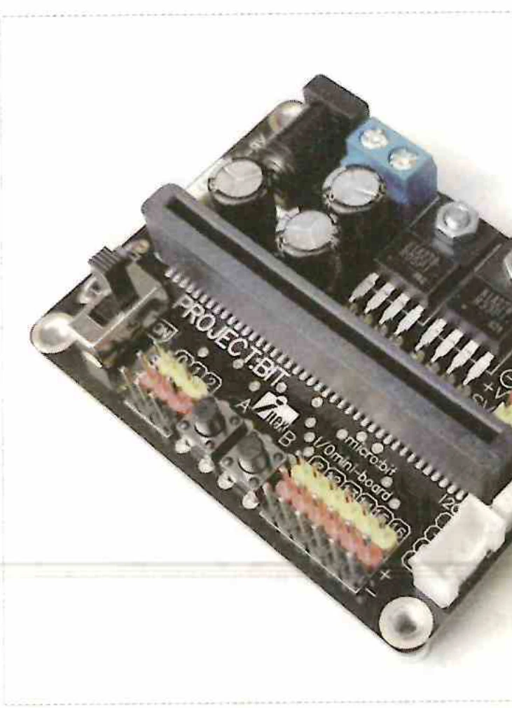
Hover or tap the Edge Socket, 4-Channel Servos, or DC Regulator on PROJECT:BIT to explore.
AX-microBIT+ (#830032) Activity Board Anatomy
Interactive Map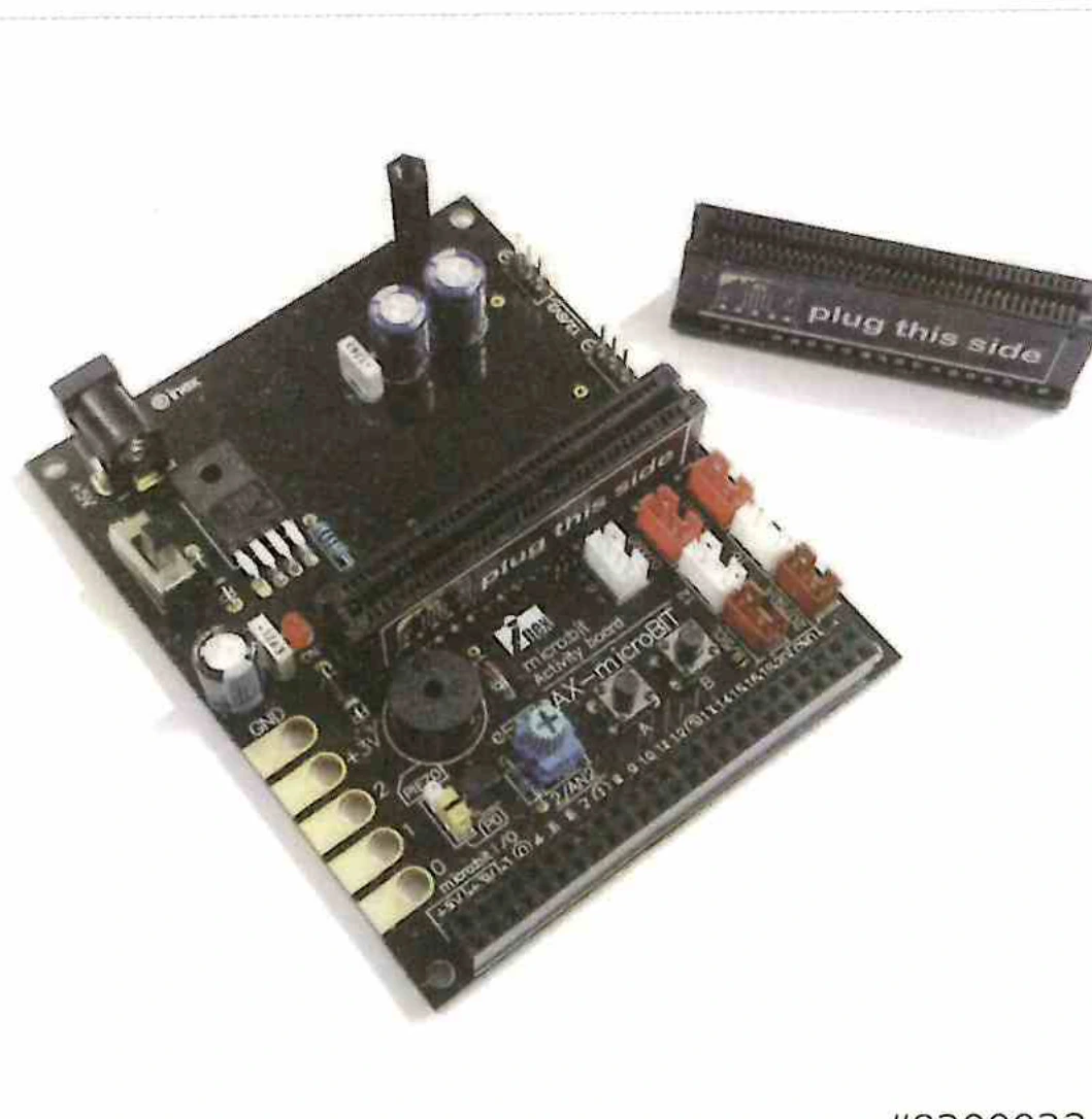
Hover or tap the Banana Jacks, Potentiometer, or DC Power Jack on AX-microBIT+ to explore.
iBIT+ (#8000480) Robotics Controller Anatomy
Interactive Map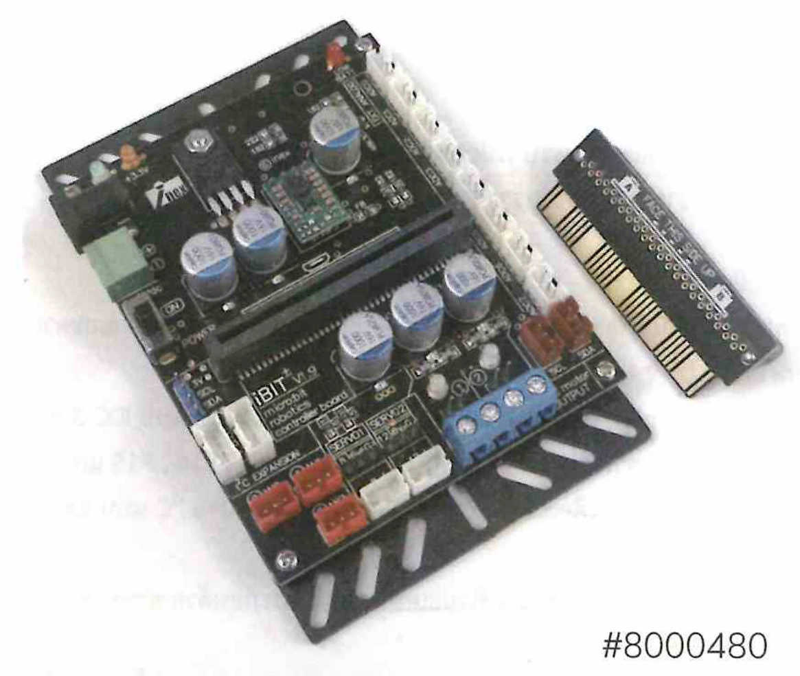
Hover or tap the Dual Motor Drivers, ADS7828 12-bit ADC, or Servo ports on iBIT+ to explore.
Expansion Boards Review & Self-Check
- Check what you remember about why an expansion board is needed, and what each of the three INEX boards is built for.