Chapter 7
Reading Analog Signals
อ่านค่าสัญญาณแอนะล็อก
- Both micro:bit V1 and V2 can read analog signals (สัญญาณแอนะล็อก) on 6 pins: P0, P1, P2, P3, P4 and P10.
- A built-in converter turns the voltage into a number with 10-bit resolution.
- The number runs from 0 to 1023, for an input voltage of 0 to 3.3 V.
7.1 10-Bit ADC Architecture อ่านค่าแอนะล็อกผ่านขาพอร์ต P0, P1 และ P2
- An Analog-to-Digital Converter (ADC) (วงจรแปลงสัญญาณแอนะล็อกเป็นดิจิทัล) measures a voltage.
- It gives back a whole number that your code can use.
The scale: number against voltage
- 10 bits give 210 = 1024 levels, so the numbers are 0 to 1023.
- Smallest step: 3.3 V ÷ 1023 ≈ 3.2 mV.
- Halfway (512) is about 1.65 V.
| Analog Property | Technical Specification (ข้อกำหนดทางเทคนิค) |
|---|---|
| ADC Resolution | 10-bit: 210 = 1024 levels (numbers 0 to 1023) |
| Input Voltage Range | 0 V to 3.3 V (0 V = 0, 3.3 V = 1023) |
| Step Resolution | 3.3 V ÷ 1023 ≈ 3.2 millivolts (mV) per count |
| Analog Input Pins | 6 pins: P0, P1, P2, P3, P4 and P10 |
| Write-Only (PWM) Pins | 11 pins: P5, P6, P7, P8, P9, P11, P12, P13, P14, P15, P16 |
Where the pins are ตำแหน่งขา P0, P1, P2
Safe voltages
⚠️ Be careful: you can destroy the board
- The micro:bit's circuits accept 3.3 V at most.
- Never connect 5 V, 9 V, 12 V or mains power to P0, P1 or P2. The chip burns out for good.
- AA or AAA cells (1.5 V alkaline, 1.2 V rechargeable) are under the limit, so you can read them directly.
MakeCode block: analog read pin [P0]
- It returns a digital number from 0 to 1023 for the pin you choose.
- Try it: move the "Voltage on P0" slider and watch the count change.
💻 7.1 Reading the raw ADC count on pin P0
forever
show number analog read pin P0
pause (ms) 1000
See it in JavaScript
basic.forever(function () {
	basic.showNumber(pins.analogReadPin(AnalogPin.P0))
	basic.pause(1000)
})7.2 DIY Battery Tester Project ทดสอบแรงดันไฟฟ้าแบตเตอรี่
- An alkaline or rechargeable AA or AAA cell gives about 1.2 to 1.5 V.
- That is under the micro:bit's 3.3 V limit, so the board can read it directly.
Physical wiring setup การต่อวงจร
- You need only 2 things: a micro:bit V2 and 2 crocodile clips.
- Step 1 — Red clip (positive): clip the P0 ring to the + end of the battery.
- Step 2 — Black clip (ground): clip the GND ring to the − end of the battery.
- Step 3 — Power the board: use a micro USB cable to a computer, or a 3 V battery pack on the JST connector at the back.
Voltage Calculation Formula & Program สูตรการคำนวณและโค้ดการทำงาน
Formula for the measured voltage:
voltage = (ADC count × supply voltage of the micro:bit) ÷ maximum ADC count
V = (ADC × 3.3) ÷ 1023
Worked example ตัวอย่างการคำนวณ
- The
analog readblock gives 465. What is the voltage, and is the battery good?
- Step 1 — Multiply: 465 × 3.3 = 1534.5
- Step 2 — Divide: 1534.5 ÷ 1023 = 1.5 V
- Step 3 — Compare: 1.5 V is 1.2 V or more, so the display shows the tick.
Evaluation criteria การประเมินสภาพแบตเตอรี่
- 1.2 V or more: the battery still has power →
show icon (Yes). - Below 1.2 V: the battery is worn out →
show icon (No).
The textbook program การทำงานของโปรแกรม
- on start: show the text
"Battery Tester". - Button B: show the raw ADC count. It does not yet tell you good or bad.
- Button A: read P0, convert to volts and scroll the voltage.
- Then show a tick if the voltage is 1.2 V or more, or a cross if it is lower.
- The voltage scrolls with all its decimals (like 1.45161290323), so the tick or cross comes a moment later.
💻 7.2 Battery tester — count on B, volts and verdict on A
on start
show string Battery Tester
on button B pressed
show number analog read pin P0
on button A pressed
set Voltage to (analog read pin P0 × 3.3) / 1023
show number Voltage
if Voltage < 1.2 then
show icon
else
show icon
See it in JavaScript
let Voltage = 0
basic.showString("Battery Tester")
input.onButtonPressed(Button.B, function () {
	basic.showNumber(pins.analogReadPin(AnalogPin.P0))
})
input.onButtonPressed(Button.A, function () {
	Voltage = pins.analogReadPin(AnalogPin.P0) * 3.3 / 1023
	basic.showNumber(Voltage)
	if (Voltage < 1.2) {
		basic.showIcon(IconNames.No)
	} else {
		basic.showIcon(IconNames.Yes)
	}
})Real Physical Battery Tester Hardware Setup
- This photo shows a real micro:bit V2 wired to an alkaline AA battery with crocodile clips.
- Hover over or tap each part to see its physical and electrical role.
Real micro:bit V2 Battery Voltage Tester Setup
Interactive Map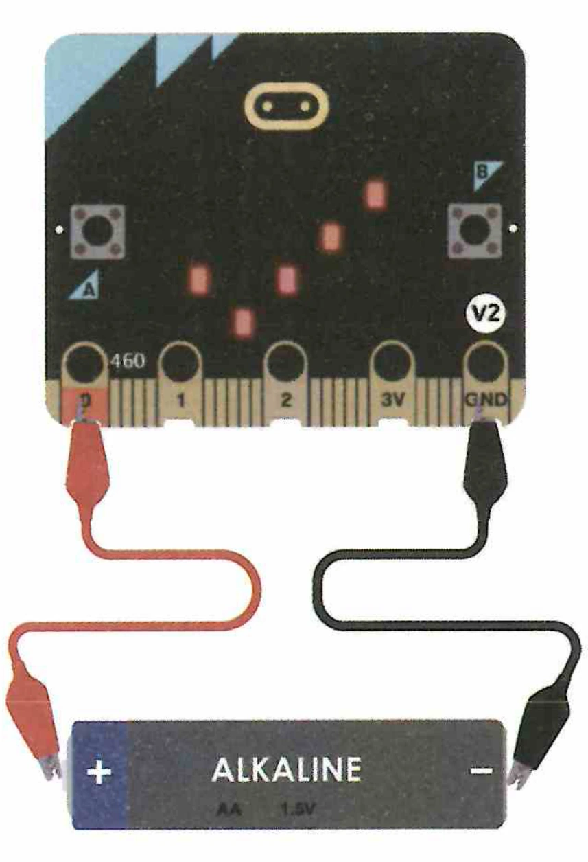
Hover or tap the 5x5 LED Matrix, P0 (+) Clip, GND (-) Clip, 1.5V Battery, or Terminals to inspect the physical testing circuit.
Chapter 7 Review & Self-Check
- Check your understanding of the 10-bit ADC, safe voltages, the voltage formula and battery checks.